AKAI M-7 amp saturator
The story begins with the fact that I was approached by a friend to modify the vacuum tube amplifiers of the Akai M-7 tape recorder. Among connoisseurs such amplifiers are known as great saturators/overdrive amps for run the signal through them.
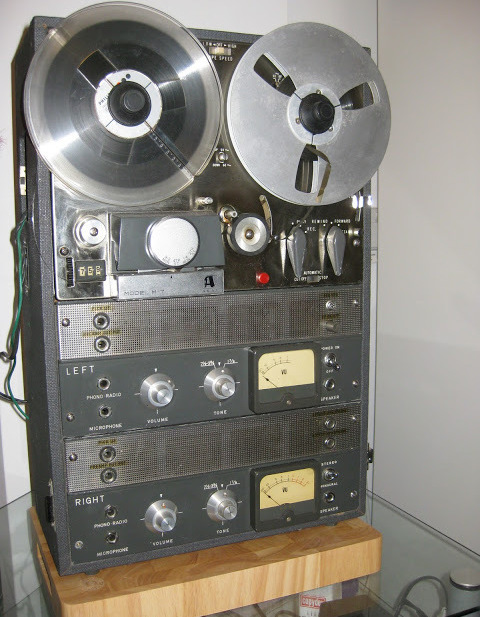
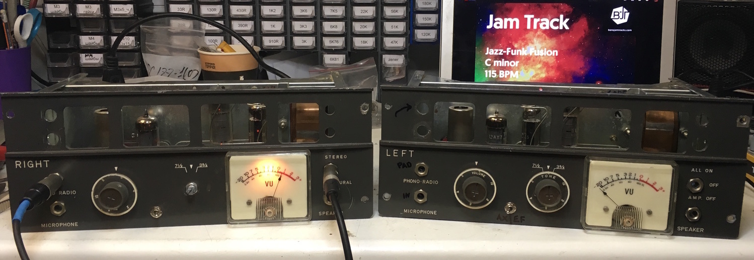
In the original M-7 / M-8 family amplifiers are used to amplify and transmit signal the recording head in the recording mode or in the playback mode to amplify and transmit signal from the playback head to the build-in speakers. The advantage of these recorders is the fact that the amplifiers are made in the form of removable modules which is convenient for their replacement and maintenance.
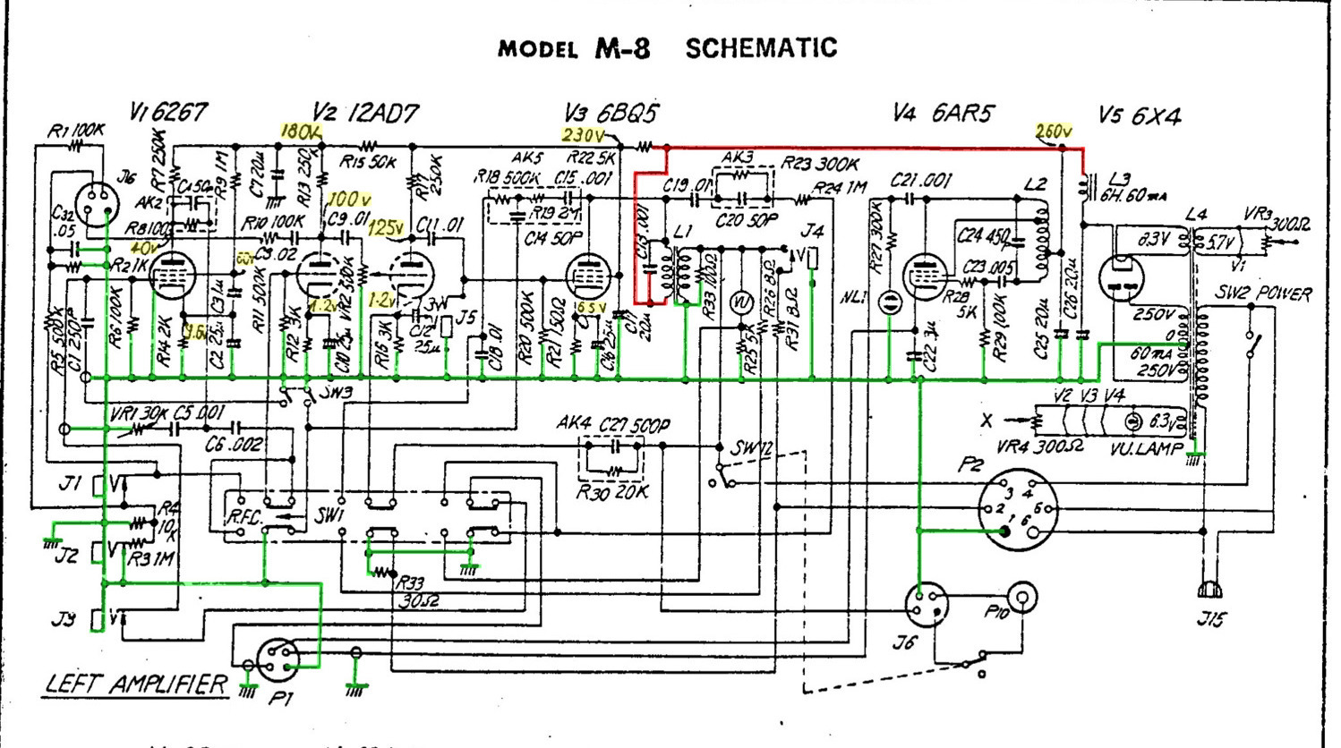
Electric circuitry is typical for equipment of the 60’s - pre-amplifier stage on 12AX7 and EF86 lamps (for two different modes) and an output stage on EL84. This scheme is very similar to the low-power guitar amplifier, and in fact these tape recorders are remade in such amplifiers.
I’ve found cool recourse that helped me to got some additional information about modding M-7.
The main tasks in the process of alteration were:
- to get rid of heavy and unnecessary tape mechanism, as well as all the circuit stages associated with the tape and magnetic heads
- to modify the circuit so that the device can receive and output line level signals
- to set the transition transformer for 220VAC, as devices are fixed at 100 / 110V
- to pack the construction in the native case, but shortening it in height
The first thing you need to unscrew and unsolder all unnecessary. The result was a bunch of wires and mechanics.
When the first amp was moded it turned out that:
- the original tone adjustment potentiometer has very little effect
- the output amplifier is capable of producing several watts for 8Ohm load, which is too much for the subsequent connection to the audio interface/mixer with line input.
Also, since there are two input tubes, it was decided to make a switch between them for different timbre and slightly different gain (EF86 louder).
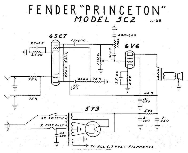
More complete adjustment of tones was borrowed from a Fender Princeton schematic.
The combination of resistors for a more convenient output level was found empirically.
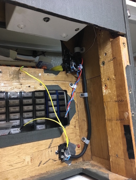
Since the construction was supposed to install a transient transformer with 220V to 110V, so it was an experiment to determine the location with the least influence of network backgrounds on amplifiers. This place was located at the top right corner of the amp. Just to minimize the interference noises, it was decided to make the power wiring with shielded wire.
As a result of all the manipulations, the final device looks like this:
A small videoclip as an example:
Akai M-7/M-8 tube overdrive machine
Обработка видео...